


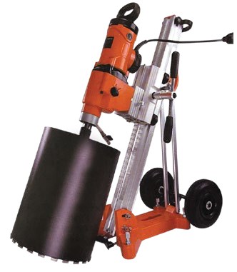
A concrete core drilling machine removes a cylindrical sample from hardened concrete for direct examination and compression testing. Coring is used when standard cubes are missing or doubtful, when in-place strength must be verified, or when an older structure requires assessment.
Why Take Concrete Cores?
A core reveals the concrete actually placed, including the effects of compaction, curing and site conditions. It can confirm strength in a disputed region and expose voids, segregation or unusual aggregate. A core result is not directly interchangeable with a standard moulded specimen because geometry, drilling damage, moisture and reinforcement affect it.
Use non-destructive screening to select representative locations and minimise holes. A rebound hammer survey maps surface hardness, while ultrasonic pulse velocity testing can identify variability. Neither substitutes for a core strength result.
Machine and Accessories
A stable rig carries a diamond core barrel on a guided feed. Water cools the segments, removes slurry and limits dust. Anchor fixing gives positive restraint; a vacuum base is useful only on sound, smooth surfaces with a maintained seal. Provide residual-current electrical protection, controlled drainage and guards.
Common barrel diameters are 50–150 mm. Core diameter should be at least three times the nominal maximum aggregate size, and 100 mm is a common practical choice. Smaller cores may be necessary in congested structures but increase variability. Check usable drilling depth, motor speed, stand travel, mounting method and availability of replacement barrels.
Specify the drilling rig around the deepest 150 mm barrel assembly and the confined locations where samples will actually be taken. Motor torque and speed must suit reinforced concrete and the selected diamond bond, while stand travel must clear the completed core without dismantling the anchor. Confirm vacuum-pad performance only for sound, smooth surfaces; retain mechanical anchoring for rough or vertical work. Provide a residual-current device, water-flow control, slurry collection and a safe method of handling the core at breakthrough. Stock barrel segments, arbor seals, anchor consumables and feed-carriage wear parts. A compatible covermeter is essential because consumable cost is minor compared with cutting an undocumented bar.
Location and Drilling Practice
Review drawings, loading and permissions with the responsible engineer. Scan for reinforcement and services using a covermeter before drilling. Avoid bars wherever possible, keep clear of edges and joints, and never core a load-critical region without structural approval. Mark orientation and specimen identity before extraction.
Mount the rig rigidly and drill perpendicular to the surface with steady feed and continuous water. Excessive pressure polishes segments, overheats the bit and can crack the core. Catch the sample before it falls, record any bar encountered and photograph the hole and recovered material. Patch approved holes with compatible non-shrink grout after inspection.
Specimen Preparation and Test
Inspect and measure the core, then trim damaged ends. Grind or cap bearing surfaces so they are plane and perpendicular to the axis. A length-to-diameter ratio from 1.0 to 2.0 is used, with the applicable correction factor recorded. Note moisture conditioning, drilling direction, aggregate size and any reinforcement.
Test prepared specimens under EN 12504-1 or ASTM C42 using the procedures linked in our concrete compression test guide. Report measured core strength and every correction separately. Interpretation for characteristic in-situ strength belongs to the assessment standard and engineer, not to a single generic conversion.
Assign the core identifier, member, depth and drilling orientation before trimming removes field marks. Measure diameter in orthogonal directions and determine length after end preparation, since the final L/D controls the stated correction. Record visible voids, drilling fractures, embedded steel and aggregate size on the specimen sheet. The grinding machine must produce parallel bearing faces without overheating or loosening particles. Preserve the selected moisture condition during storage and transport; an unrecorded drying interval can shift strength. Before compression, check that the machine range suits the smaller loaded area and that the core is centred. Report raw failure load separately from corrected strength so the assessment remains auditable.
Sampling Plan and Limitations
A sampling plan should cover distinct pours, members and areas indicated by screening. Three or more cores per test region is typical, subject to EN 13791 or the engineer’s specification. One result cannot represent a large structure. Avoid cherry-picking only high rebound readings or convenient access points.
Coring creates a local opening and may cut reinforcement if poorly planned. A 100 mm hole is normally repairable with non-shrink grout, but damage in a highly stressed section can be significant. Isolate services, control slurry and dust, secure work at height and document repair materials. Preserve raw dimensions, failure photographs and machine records with the report.
Common Errors & How to Avoid Them
- Drilling before scanning can sever reinforcement or services; map the proposed hole with a covermeter and review it against drawings.
- A loose anchor or leaking vacuum base lets the barrel wander, producing a tapered or fractured core; prove the mounting before engaging concrete.
- Choosing a diameter below three times the aggregate size increases result variability; use a larger barrel unless structural constraints are documented.
- Excessive feed pressure overheats diamond segments and induces microcracking; maintain cooling water and let the barrel cut at a steady rate.
- Testing ragged ends introduces eccentric stress; trim and grind or cap them to the required planeness and perpendicularity.
- Losing orientation and depth data prevents meaningful structural interpretation; mark the core immediately and photograph extraction.
Do not count embedded bar as ordinary specimen material without applying the governing assessment rules. Protect recovered cores from drying or saturation changes during transport, and record any break that occurred during removal. Patch only after the engineer has inspected the opening and confirmed the specified repair system.
Frequently Asked Questions
Does core drilling damage the structure?
A 100 mm core hole is normally patched with non-shrink grout, but load-critical sections and reinforcement must be avoided through engineering review and scanning.
How many cores are needed?
Typically at least three cores are taken per test region; follow EN 13791 and the responsible engineer’s specification for the final sampling plan.
Recommended Apparatus
NL Scientific manufactures the Coring Machine (HEAVY Duty) for this method. Browse the full Concrete Testing Equipment range or request a quotation from our engineers.
